
Here the second article (first one is HERE) about how to render real time 3D stuff on a RGB LED matrix panel with a Raspberry Pi. In this article, we’ll look at the hardware interface between the Raspberry Pi and the RGB LED matrix display: the RGB Matrix HAT.
The RGB Matrix HAT is an additional card designed to drive RGB LED matrix panels with the HUB75 interface. The HAT does not work with other interfaces like the HUB12 (used for monochrome LED matrix displays). The RGB Matrix HAT is plugged directly on the 40-pin GPIO connector of the Raspberry Pi 2 or 3. An IDC cable is then connected from the HAT to the LED matrix panel.
The HAT requires an additional power input (5V) for powering the matrix HAT itself. This additional power input is provided by a 5.5mm (outer) / 2.1mm (inner) barrel jack connector.
The GPIO connector of the Raspberry Pi works with a logic voltage of 3.3V. A RGB LED matrix panel needs 5V. The main goal of the HAT is to translate the 3.3V of the GPIO to the 5V required by the LED panel (this conversion is done by HTC245 chips on the HAT). The other function of the HAT is to protect the GPIO of the RPi from overloading.
Links:
- Adafruit RGB Matrix HAT + RTC for Raspberry Pi – Mini Kit
- Adafruit RGB Matrix HAT for Raspberry Pi – Tutorial
The RGB Matrix HAT bundle includes the matrix HAT PCB (printed circuit board) and three connectors (one for the 40-pin GPIO, a second one for the HUB75 interface and the last one for the output power supply –this last one is not required if the LED panel is directly powered by an external power supply unit) that must be soldered to the PCB. Soldering the connectors is the biggest difficulty if you have never soldered or does not have the hardware. But if you have the soldering iron, you should solder all points in less than 30 minutes…


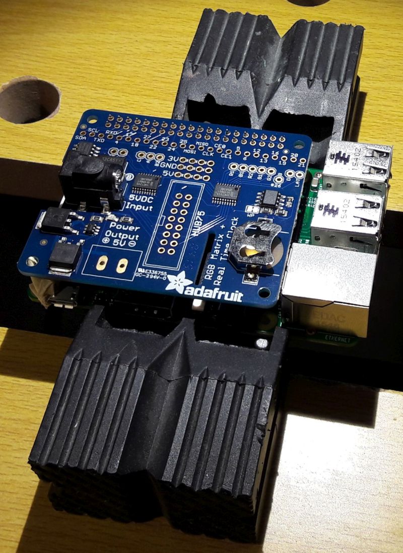
The HAT ready for the soldering session: the 40-pin connectior of the HAT is plugged on the RPI’s GPIO. That will make the soldering easier.
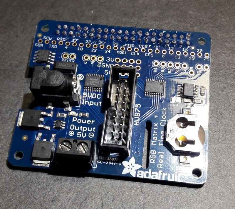
After around 20 min, all connectors were soldered:
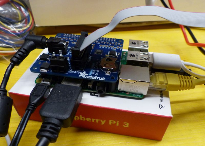
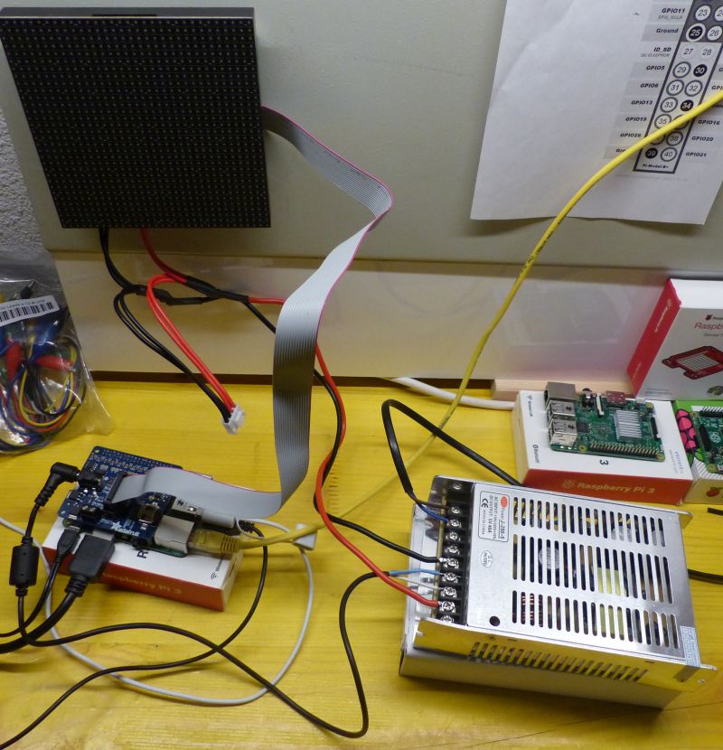
And few minutes later, the HAT is connected to the RPi, to the Matrix panel and to the power supply:
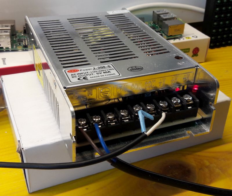
To power the HAT board and the LED panel, I found this model of power supply at my local dealer: 5V and 40A.
Here is an overview of the how the different devices are connected:

In the next article we will see how to control the LED lighting by code (Lua or Python) with GeeXLab to draw simple things.